
Thin-Wall Model Printing Guide: How to Avoid Internal Structure Marks on the Outer Wall in 3D Printing
 Release date:
  Estimated reading time: 7 minutes
During FDM 3D printing, thin-wall models are generally more sensitive to slicing parameters than models with normal wall thickness. Especially when printing thin-wall parts, shells, structural components and lightweight models where surface quality matters, apparent lines, shadows or localized bumps corresponding to the internal structure may appear on the outer wall even when the model geometry itself is correct, degrading the final surface quality. This phenomenon is especially common with default slicing parameters. On models with normal wall thickness, such slight material overflow is usually not noticeable, but when the wall is thin, the squeezing between internal print lines affects the outer wall more directly, so the defect is significantly amplified. Based on real print tests, this article analyzes why internal structure marks appear on the outer wall of thin-wall models and introduces several effective parameter adjustments.
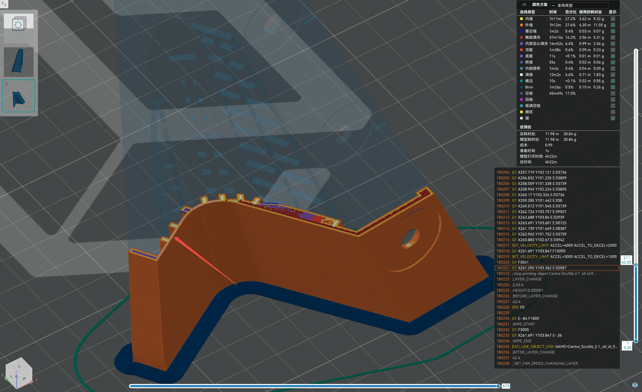
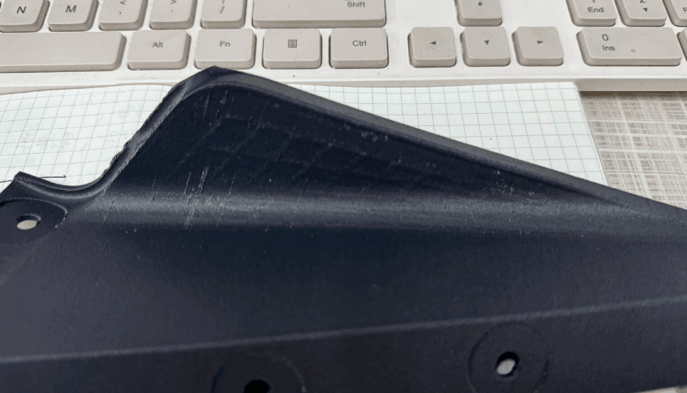
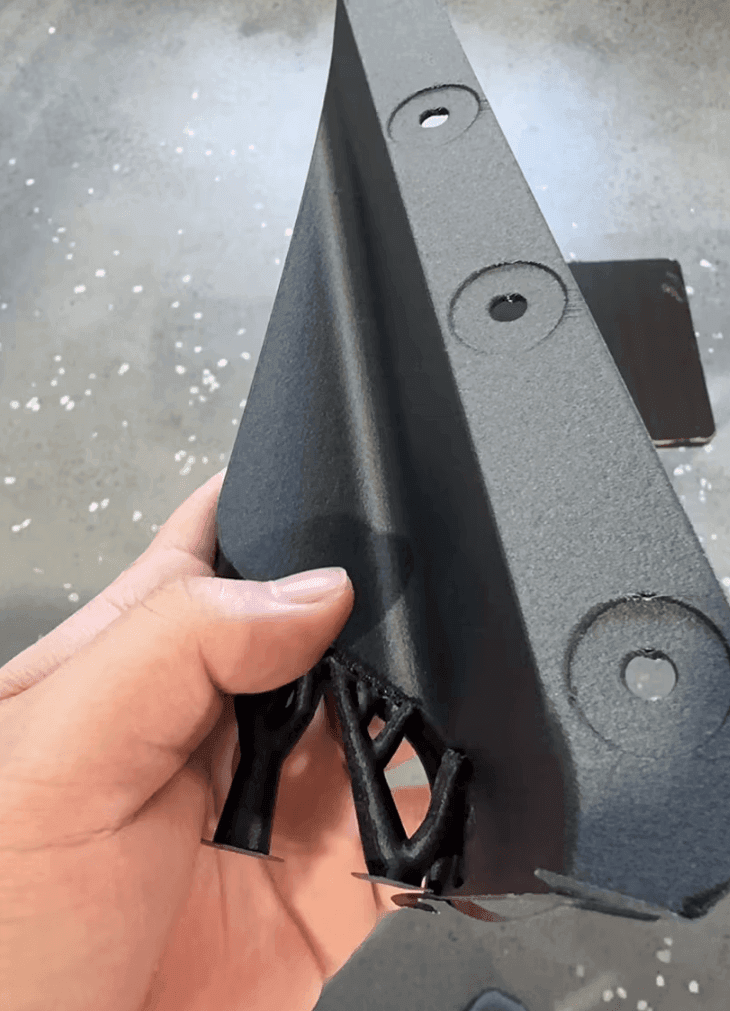
Result of the actual print
1. Why do thin-wall models easily show internal structure marks?
Visible lines on the outer wall of a thin-wall model do not necessarily mean insufficient mechanical precision of the printer, nor a problem with the model surface itself. One major cause is the squeezing between print lines and the overflow of material flow. During FDM printing, the nozzle extrudes molten material layer by layer along the slicing path. When printing an inner wall, the material needs to bond with adjacent lines to a certain degree. If the lines overlap heavily, the extruded material gets squeezed by neighboring print lines. For models with normal wall thickness, excess material is usually absorbed by the internal space and is hardly visible from the outside. In thin-wall models, however, the internal space is limited and the distance between the inner and outer walls is small. When the excess flow produced while printing the inner wall cannot be released inward, it may be squeezed outward and overflow, causing slight bumps or textures on the outer wall. In short, the problem can be understood as: Print lines squeeze each other → excess material overflows → the overflow affects the outer wall → internal structure marks are “mapped” onto the outer wall. Real tests also show that the impact of flow overflow becomes more obvious in thin-wall structures, where the inner and outer walls are close to each other.
2. When does the problem become more obvious?
Internal structure marks on thin-wall models are usually related to the following factors:
1. Thin model walls
The thinner the wall, the smaller the distance between the internal print path and the outer wall, and the more obvious the influence of internal material on the outer wall.
2. Excessive flow
If the actually extruded material exceeds the theoretical requirement, the excess material increases the squeezing between lines and raises the possibility of outward overflow.
3. Wall overlap set too high
Some overlap between the inner and outer walls is normally required to ensure good bonding between print lines. But on thin-wall models, too much overlap can cause local material accumulation.
4. Unsuitable inner/outer wall print order
The print order of inner and outer walls affects how material is distributed within the limited space, so changing the print order can sometimes reduce the influence on the outer wall.
3. Three ways to fix outer wall marks on thin-wall models
To address this issue, we ran multiple parameter tests, mainly adjusting line width and flow, the inner/outer wall print order, and the wall overlap.
Method 1: Adjust line width and flow
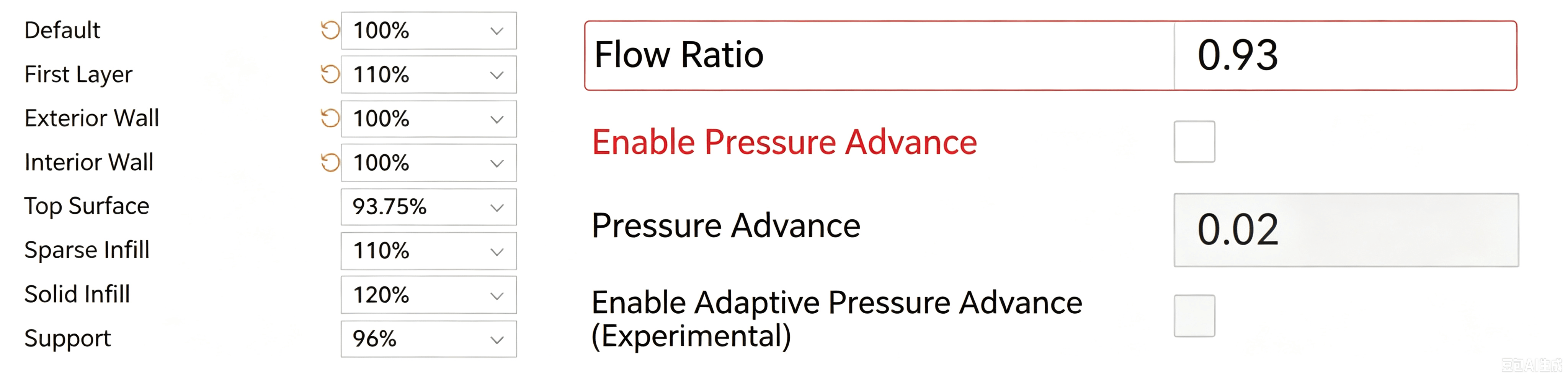
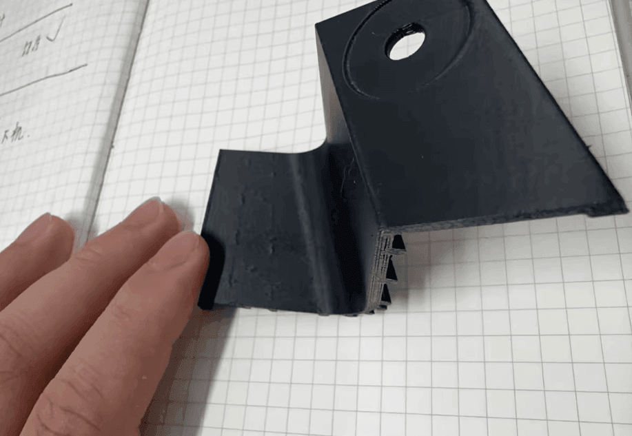
Result: the overflow defect was reduced, but not eliminated.
You can first try lowering the print flow to reduce the amount of material actually extruded. When the flow is too high, each print line extrudes more material, making lines squeeze each other more easily. Lowering the flow therefore reduces the excess material that overflows toward the outer wall. Line width can be adjusted in combination with the flow. Note that lower is not always better. Too little flow may cause:
insufficient bonding between walls
visible gaps
localized under-extrusion
reduced model strength
A more reasonable approach is to adjust step by step according to the actual print results of the thin-wall model, instead of cutting the flow drastically in one go. In the actual tests, adjusting line width and flow reduced the overflow defect on the outer wall, but did not completely solve the problem. This shows that for thin-wall models, flow adjustment alone is often not enough.
Method 2: Change the inner/outer wall print order
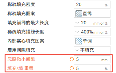
The second method is to change the printing order of the inner and outer walls. Different print orders change the squeezing relationship between the walls and affect the final surface condition of the outer wall. If the outer wall is easily affected by the inner wall material under the current slicer configuration, try swapping the inner/outer wall print order and run small-scale tests again. The advantage of this method is that it usually does not require major changes to the overall printing parameters, making it a low-risk optimization for an already stable print configuration. Test results show that changing the inner/outer wall print order reduced the overflow defect on the outer wall, but again did not completely solve the problem. The print order can therefore serve as an auxiliary optimization, but for severe outer wall marks, the wall overlap relationship still needs further adjustment.
4. The most effective method: reduce the wall overlap
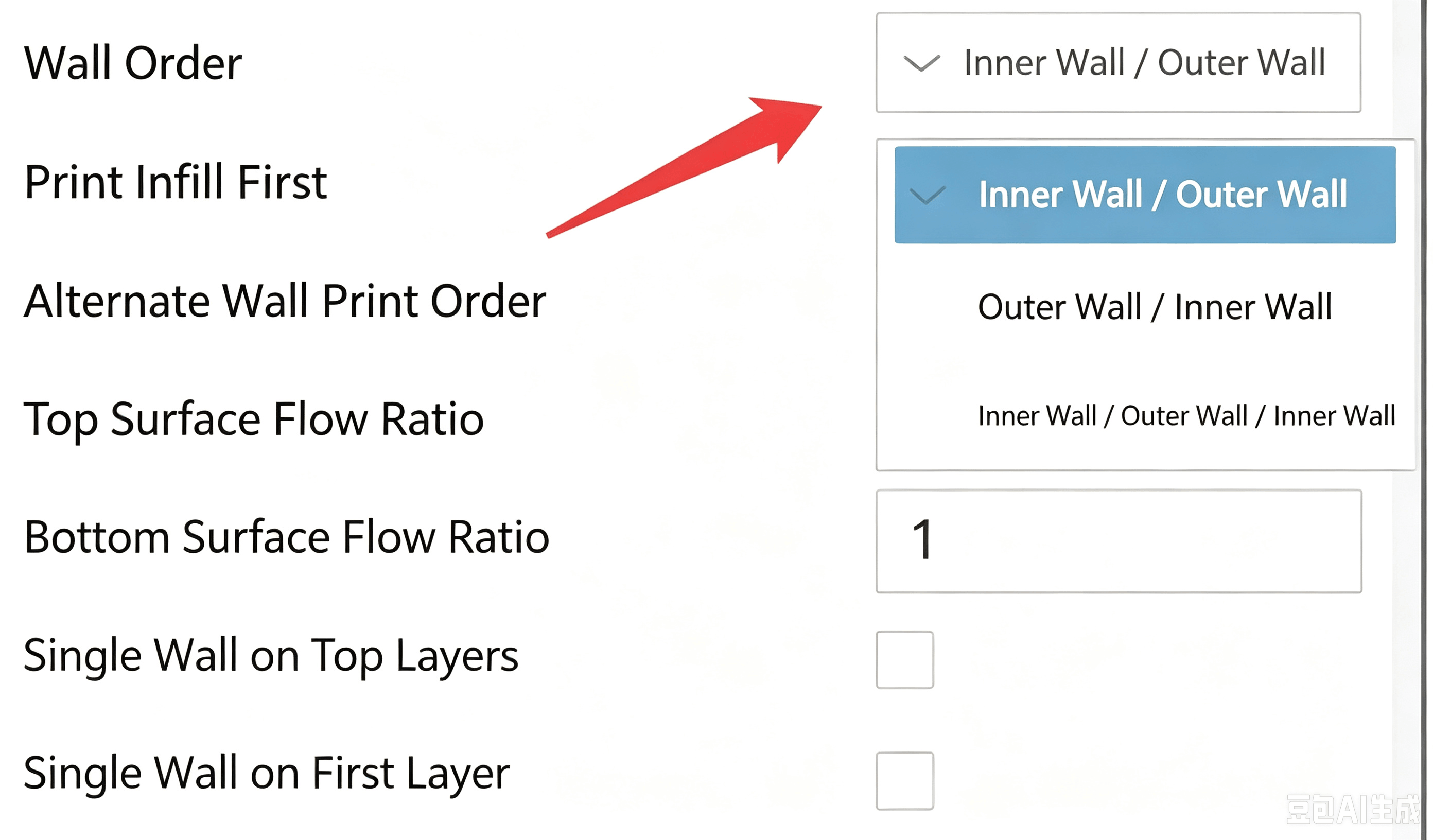
In the actual tests, the third method brought the most obvious improvement. The wall overlap determines how strongly different print lines bond to each other. Proper overlap ensures a good connection between walls, but if it is set too high on a thin-wall model, more material gets packed into the limited space. This increases the squeezing between print lines and pushes excess material outward. Therefore, for thin-wall models with obvious internal structure overflow, try appropriately reducing the wall overlap. Test results show that after reducing the overlap, the internal structure marks on the model surface improved significantly, and the surface defect in the test was finally solved. This also shows that for thin-wall models, higher wall overlap is not necessarily better; a proper balance should be found between structural bonding, printing stability and surface quality.
5. Recommended tuning workflow for thin-wall models
If internal structure lines appear on the outer wall of a thin-wall model, avoid changing many parameters at once. A more reasonable approach is to troubleshoot step by step, from simple to complex.
Step 1: Check the flow
First confirm whether the flow is reasonable for the current material and nozzle configuration. If obvious over-extrusion exists, reduce the flow ratio appropriately and observe whether the outer wall texture weakens.
Step 2: Check the wall overlap
If reducing the flow helps little, check the wall overlap next. For thin-wall models, try lowering the overlap appropriately to reduce unnecessary squeezing between the inner and outer walls.
Step 3: Try changing the inner/outer wall print order
If local textures still exist, test different inner/outer wall print orders.
Step 4: Run small-scale tests
Do not repeatedly print the full model. Instead, cut out the area where the problem is most likely to appear and print a small test piece. This greatly shortens test time and reduces material consumption.
6. Do not simply chase a higher overlap
A common misconception about thin-wall models is that a higher overlap makes the walls bond more firmly, so the overlap should be as high as possible. In fact, the overlap needs to be adjusted according to the model structure. For models with thick walls, the internal space can absorb a certain amount of excess material, so slight overflow usually does not affect the appearance. For thin-wall models, however, the space between the inner and outer walls is much more limited. Excessive overlap may cause material to accumulate locally, producing surface bumps, textures or even visible internal structure outlines. Therefore: the goal of overlap is not to make it as high as possible, but to avoid excessive squeezing while keeping the walls well bonded.
7. How to balance surface quality and model strength?
Reducing the flow or wall overlap can improve the outer wall surface, but over-adjustment may also affect the model strength. Therefore, during actual printing, three indicators need to be observed at the same time: ① Outer wall surface quality Are internal structure lines, local bumps or uneven areas still visible? ② Wall bonding Are there obvious gaps or insufficient bonding between print lines? ③ Overall model strength After the adjustment, does the model still meet the actual use requirements? If the model is mainly for display, appearance verification or prototyping, focus more on surface quality; if it is a load-bearing structural part, find a reasonable balance between surface quality and structural strength.
8. Summary of thin-wall printing parameter optimization
The tests show that internal structure marks on the outer wall of thin-wall models are mainly related to the squeezing between print lines and the overflow of excess material. On models with normal wall thickness this phenomenon is usually not noticeable, but thin-wall structures amplify it, so slicing parameters need to be optimized according to the model characteristics. The main conclusions of this test are as follows:
Adjustment | Test result | Recommendation |
|---|---|---|
Adjust line width and flow | Defect reduced, but not fully solved | ★★★ |
Change inner/outer wall print order | Defect reduced | ★★★ |
Reduce the wall overlap | Surface clearly improved, defect solved | ★★★★★ |
Therefore, when internal structure marks appear on the outer wall of a thin-wall model, start troubleshooting from flow, wall overlap and the inner/outer wall print order. Among them, for the thin-wall overflow problem in this test, appropriately reducing the wall overlap brought the most obvious improvement.
Conclusion
The print quality of thin-wall models depends not only on the 3D printer itself, but also on how well the slicing parameters and the model structure match each other. When internal structure marks appear on the outer wall, do not simply blame the printer's precision. Analyzing material flow, line width, wall overlap and the inner/outer wall print order helps locate the source of the problem more accurately. For FDM 3D printing, stable print results come from a proper match between the printer, material, model and slicing parameters. Especially when printing thin-wall parts, precision housings and high surface quality models, targeted parameter optimization can effectively reduce surface defects caused by material overflow and deliver a more uniform, smoother outer wall.